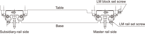
| Mounting Procedure |
| [Example of Mounting the LM Guide When an Impact Load is Applied to the Machine and therefore Rigidity and High Accuracy are Required] |
|
|
| When an Impact Load is Applied to the Machine |
| ●Mounting the LM Rail(s) |
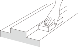
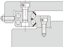
| (1) | Be sure to remove burr, dent and dust from the mounting surface of the machine to which the LM Guide is to be mounted before installing the LM Guide. ( Image ) |
| Note) | Since the LM Guide is coated with anti-rust oil, remove it from the reference surface by wiping the surface with washing oil before using the guide. Once the anti-rust oil has been removed, the reference surface is prone to getting rusted. We recommend applying low-viscosity spindle oil. |
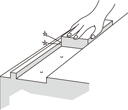 |
| Checking the Mounting Surface |
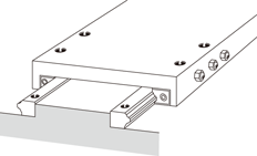
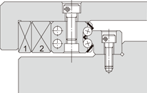
| (2) | Gently place the LM rail onto the base, and temporarily secure the bolts to the extent that the LM rail lightly contacts the mounting surface (align the line-marked side of the LM rail with the side reference-surface of the base). ( Image ) |
| Note) | The bolts for securing the LM Guide must be clean. When placing the bolts into the mounting holes of the LM rail, check if the bolt holes are displaced.( Image ) Forcibly tightening the bolt into a displaced hole may deteriorate the accuracy. |
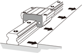 |
| Aligning the LM Rail with the Reference-Surface |
|
|
|
| Checking with the Bolt for an Allowance |
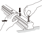
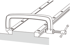
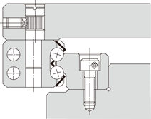
| (3) | Secure the set screws for the LM rail in order with a tightening force just enough to have the rail closely contact the side mounting surface. ( Image ) |
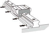 |
| Tightening the Set screws |
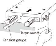
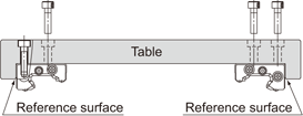
| (4) | Tighten the mounting bolts at the designated torque using a torque wrench. (See Image , and Table and Table on General Catalog.) |
| Note) | To achieve stable accuracy when tightening the LM rail mounting bolts, tighten them in order from the center to the rail ends. |
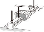 |
| Fully Fastening the Mounting Bolts |
| (5) | Mount the other rail in the same manner to complete the installation of the LM rails. |
| (6) | Hammer in caps into the bolt holes on the top face of each LM rail until the top of the cap is on the same level as the top face of the rail. |
| ●Mounting the LM Blocks |
| (1) | Gently place the table on the LM blocks and temporarily fasten the mounting bolts. |
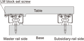
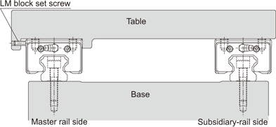
| (2) | Press the master side LM blocks to the side reference surface of the table using set screws and position the table. (See Image on General Catalog.) |
| (3) | Fully fasten the mounting bolts on the master side and the subsidiary side to complete the installation. |
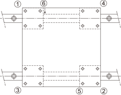
| Note) | To evenly secure the table, tighten the mounting bolts in diagonal order as shown in Image . |
| This method saves time in establishing straightness of the LM rail and eliminates the need to machine securing dowel pins, thus to drastically shorten the installation man-hours. |
|
| Sequence of Tightening the LM Blocks |
| [Example of Mounting the LM Guide When the Master LM Rail is not Provided with Set screws] |
|
| When the Master LM Rail is not Provided with Set screws |
| ●Mounting the Master LM Rail |
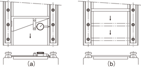
| After temporarily fastening the mounting bolts, firmly press the LM rail to the side reference surface at the position of each mounting bolt using a small vice and fully fasten the bolt. Perform this in order from either rail end to the other. ( Image ) |
|
| ●Mounting the Subsidiary LM Rail |
| To mount the subsidiary LM rail in parallel with the master LM rail, which has been correctly installed, we recommend adopting the methods below. |
| ■Using a Straight-edge |
| Place straight-edges between the two rails, and arrange the straight-edges in parallel with the side reference surface of the master LM rail using a dial gauge. Then, secure the mounting bolts in order while achieving straightness of the subsidiary rail with the straight edge as the reference by using the dial gauge. ( Image ) |
|
| ■Using Parallelism of the Table |
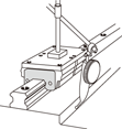
| Secure the two LM blocks on the master LM rail with the table (or a temporary table for measurement), and temporarily fasten the LM rail and the LM block on the subsidiary LM rail with the table. Place a dial gauge to the side face of the LM block on the subsidiary rail from the dial stand fixed on the table top, then fasten the bolts in order while achieving parallelism of the subsidiary LM rail by moving the table from the rail end. ( Image ) |
|
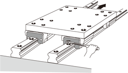
| ■Having the Subsidiary LM Rail Follow the Master LM Rail |
| Place the table on the blocks of the correctly mounted master LM rail and the temporarily fastened subsidiary LM rail, and fully fasten the two LM blocks on the master rail and one of the two LM blocks on the subsidiary rail with bolts. Fully tighten the mounting bolts on the subsidiary LM rail in order while temporarily fastening the remaining LM block on the subsidiary LM rail. ( Image ) |
|
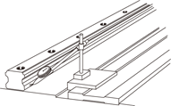
| ■Using a Jig |
| Use a jig like the one shown in Image to achieve parallelism of the reference surface on the subsidiary side against the side reference surface of the master side from one end of the rail by the mounting pitch, and at the same time, fully fasten the mounting bolts in order. ( Image ) |
|
| [Example of Mounting the LM Guide When the Master LM Rail Does not Have a Reference Surface] |
|
| ●Mounting the Master LM Rail |
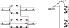
| ■Using a Temporary Reference Surface |
| You can temporarily set a reference surface near the LM rail mounting position on the base to achieve straightness of the LM rail from the rail end. In this method, two LM blocks must be joined together and attached to a measurement plate, as shown in Image . |
|
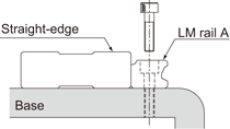
| ■Using a Straight-edge |
| After temporarily fastening the mounting bolts, use a dial gauge to check the straightness of the side reference surface of the LM rail from the rail end, and at the same time, fully fasten the mounting bolts.( Image ) |
| To mount the subsidiary LM rail, follow the procedure described on General Catalog. |
|
| [Procedure for Assembling Model HR] |
| The following procedure is recommended for assembling model HR. |
| (1) | Remove burr or knots from the LM rail mounting surface of the base using an oilstone. ( Image ) |
 |
| (2) | Use a small vice to press the two LM rails to the base so that they closely contact the reference surface, then tighten the mounting bolts to the recommended torque (see General Catalog). ( Image ) |
| a. | Check if any of the bolts has a sinking. |
| b. | Use a torque wrench to tighten the bolts in order from the center to both ends. |
 |
| (3) | Mount the LM blocks on the table, then install them onto the LM rails. Be sure the mounting bolts for the LM blocks are temporarily fastened. |
| (4) | Tighten the clearance adjustment bolt alternately to adjust the clearance. |
| If a relatively large preload is applied in order to achieve high rigidity, control the tightening torque or the rolling resistance. |
| a. | It is preferable to use three clearance adjustment bolts for each LM block as shown in Image . |
| b. | To obtain a favorable result of the clearance adjustment, set the tightening torque of the two outside screws at approx. 90% of that of the enter screw. |
 |
| (5) | Secure each LM block by gradually tightening the two LM block mounting bolts, which have temporarily been fastened, while sliding the table. ( Image ) |
|
| ●Example of Clearance Adjustment |
| Design the clearance adjustment bolt so that it presses the center of the side face of the LM block. |
| (1) | Using an adjustment screw |
| Normally, an adjustment screw is used to press the LM block. |
|
| (2) | Using tapered gibs |
| When high accuracy and high rigidity are required, use tapered gibs 1) and 2). |
|
| (3) | Using an eccentric pin |
| A type using an eccentric pin to adjust the clearance is also available. |
|
| [Procedure for Assembling Model GSR] |
| The procedure for assembling model GSR is as follows: |
| (1) | Align the table with the reference-surface of each LM block and fully fasten the mounting bolts to secure the blocks. |
| Both ends of the table must have a datum surface. ( Image ) |
 |
| (2) | Place LM rail A onto the base and align the rail with a straight-edge. |
| Fully fasten the mounting bolts using a torque wrench. ( Image ) |
 |
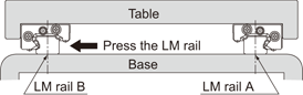
| (3) | Temporarily secure LM rail B onto the base, then mount the blocks on the rail by sliding the blocks. |
| Temporarily fasten LM rail B while pressing it toward the LM blocks. ( Image ) |
 |
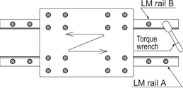
| (4) | Slide the table a few strokes to fit the LM blocks to LM rail B, then fully fasten LM rail B using a torque wrench. ( Image ) |
 |
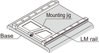
| If there are more GSR units to be assembled, we recommend producing a jig like the one shown in Image first. You can easily mount LM rails while achieving parallelism of the LM rails using the jig. |
|
| [Procedure for Assembling Model JR] |
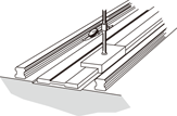
| ●Mounting the LM Rails |
| When two LM rails are to be used in parallel as shown in Image , first secure one LM rail on the base, and place a dial gauge on the LM block. Then, place the pointer of the dial gauge on the side face and top face of the other LM rail to simultaneously adjust the parallelism and the level, thus to complete mounting the LM rails. |
|
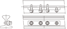
| ●Jointing LM Rails |
| When two or more LM rails are to be jointed, a special metal fitting as shown in Image is available. For such applications, specify this fitting when ordering the LM Guide. |
|
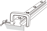
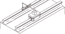
| ●Welding the LM Rail |
| When welding the LM rail, it is best to weld the LM rail while clamping it at the welding point with a small vice or the like as shown in Image . For effective welding, we recommend the following welding conditions. (During welding the LM rail, take care to prevent spatter from contacting the LM rail raceway.) |
| [Welding conditions] |
| Preheating temperature:200°C |
| Postheating temperature:350°C |
| Note) | If the temperature exceeds 750°C, the LM rail may be hardened again. |
| [For shielded metal arc welding] |
| Welding rod: LB-52 (Kobelco) |
| [For carbon dioxide arc welding] |
| Wire: YGW12 |
| Electric current: 200A |

|
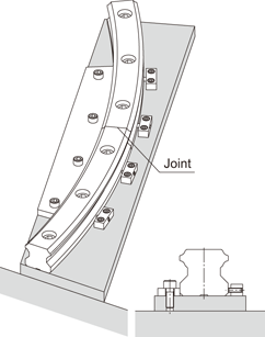
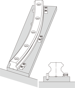
| [Procedure for Assembling Model HCR] |
| To install the LM rails of R Guide model HCR, we recommend having any form of datum point (such as a pin) on the reference side (inside) of the LM rail, and pressing the LM rail to the datum point then stopping the LM rail with a presser plate from the counter-reference surface. |
|
| Method for Securing the LM Rails at the Joint |
|
| Method for Securing the LM Rail Using a Pin
as a Datum Point |