Product information
>
LM Guide
>
LM Guide (full-ball type)
>
Separate (Four-way equal load) Model HR
>
HR
HR
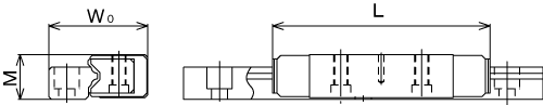
Dimensional drawing
Model No.
Outer dimensions
Basic load rating
Detail specifications
CAD
Dimensional drawing
Radial
2D (DXF)
3D
Height
M
Width
W
Length
L
Dynamic
rating
C
Static
rating
C
0
mm
mm
mm
kN
kN
HR 918
8.5
11.4
45
2.82
3.48
HR 918M
8.5
11.4
45
2.82
3.48
HR 1123
11
13.7
52
4.09
4.93
HR 1123M
11
13.7
52
4.09
4.93
HR 1530
15
19.2
69
7.56
8.77
HR 1530M
15
19.2
69
7.56
8.77
HR 2042
20
26.3
91.6
17
18.2
HR 2042M
20
26.3
91.6
17
18.2
HR 2555
25
33.3
121
33.2
35.1
HR 2555M
25
33.3
121
33.2
35.1
HR 3065
30
40.3
145
42.6
44.4
HR 3575
35
44.9
154.8
53.5
54.8
HR 4085
40
50.4
177.8
78.8
78.9
HR 50105
50
63.4
227
127
123
HR 60125
60
74.4
329
226
232
Description
*
Descriptions are pdf files.
LM Guide Classification Table
Selection Criteria
Flowchart for Selecting an LM Guide
Determining the Operating Conditions
Operating Conditions of the LM Guide
Selecting a Type
Types of LM Guides
Calculating the Applied Load
Calculating an Applied Load
Calculating the Equivalent Load
Load Rating of an LM Guide in Each Direction
Calculating the Static Safety Factor
Calculating the Average Load
Calculating the Nominal Life
Calculating the Nominal Life
Calculating the Modifi ed Nominal Life
Predicting the Rigidity
Selecting a Radial Clearance (Preload)
Service Life with a Preload Considered
Rigidity
Radial Clearance Standard for Each Model
Determining the Accuracy
Accuracy Standards
Guidelines for Accuracy Grades by Machine Type
Accuracy Standards for Each Model
Features and Dimensions of Each Model
Separate Type (4-Way Equal Load) LM Guide Model HR
Structure and Features
Types and Features
Example of Clearance Adjustment
Comparable Cross-Roller Guide Model Numbers
Dimensional Drawing, Dimensional Table
Models HR, HR-T, HR-M, and HR-TM
Standard Lengths and Maximum Lengths of LM Rails
Accessories
Lubrication Hole
Super-Rigid Full-Roller LM Guide Model HRX
Structure and Features
Types and Features
Static safety factor
Reference Error Tolerance for the Mounting Surface
Dimensional Drawing, Dimensional Table
Models HRX-C and HRX-LC
Models HRX-R and HRX-LR
Standard Lengths and Maximum Lengths of LM Rails
Tapped-Hole Type LM Rail
Lubrication hole
Design Highlights
Designing the Guide System
Examples of Arrangements of the Guide System
Method for Securing an LM Guide to Meet the Conditions
Designing a Mounting Surface
Designing a Mounting Surface
Shoulder Height of the Mounting Base and the Corner Radius
Reference Error Tolerance for the Mounting Surface
Master LM Guide Indicators and Combined Use
Options
Table of Supported Options by Models
Seal and Metal scraper
High Chemical Resistance Fluorine Seal FS
Dimensions of Each Model with Options Attached
The LM Block Dimension (Dimension L) with LaCS and Seals Attached
Overall Block Length with Fluorine Seals and Other Accessories Attached
Maximum Seal Resistance
Maximum Seal Resistance of FS
List of Parts Symbols
Dedicated Cap for LM Rail Mounting Holes
Lubrication Adapter
Removing/Mounting Jig
End Piece EP
Model No.
Model Number Coding
Notes on Ordering
Handling Precautions
LM Guide Handling Precautions
Handling Precautions for LM Guide Models for Special Environments
LM Guide for Medium-to-Low Vacuums
Handling Precautions for Optional Accessories for the LM Guide
QZ Lubricator for the LM Guide
Laminated Contact Scraper LaCS, Side Scraper for the LM Guide
Light Contact Seal LiCS for the LM Guide
High Chemical Resistance Fluorine Seal FS for the LM Guide
GC Cap
General Description
Point of Selection
Selection Flow Chart
Types and Features of LM Systems
Load Rating
Service Life of an LM System
Nominal Life
Basic Load Rating
Life Calculation Formula
Rigidity
Selecting a Clearance/Preload for an LM System
Friction Coefficient
Accuracy
Lubrication
Safety Design
Determining a Material
Surface Treatment
Contamination Protection
Features and Types
Features of the LM Guide
Large Permissible Load and High Rigidity
High Precision of Motion
Accuracy Averaging Eff ect by Absorbing Mounting Surface Error
Easy Maintenance
Substantial Energy Savings
Low Total Cost
Ideal Four Raceway, Circular-Arc Groove, Two-Point Contact Structure
Superb Error-Absorbing Capability with the DF Design
Point of Selection
Calculating the Applied Load
Calculating an Applied Load
Example of calculation
Calculating the Average Load
Example of Calculating the Average Load (1) - with Horizontal Mount and Acceleration/Deceleration Considered -
Example of Calculating the Average Load (2) - When the Rails are Movable
Calculating the Nominal Life
Example of Calculating the Nominal Life (1) - with Horizontal Mount and High-speed Acceleration
Example of Calculating the Nominal Life (2) - with Vertical Mount
Mounting Procedure
Mounting the LM Guide
Marking on the Master LM Guide and Combined Use
Mounting Procedure
Methods for Measuring Accuracy after Installation
Recommended Tightening Torque for LM Rails